*********************************************************************************************************************************************
JANUARY 2026 UPDATE
*********************************************************************************************************************************************
HYWEL THOMAS
*********************************************************************************************************************************************
ANDY LEE
*********************************************************************************************************************************************
MIKE WHITCHURCH
*********************************************************************************************************************************************
GREG BROOKES
*********************************************************************************************************************************************
KARL CROWTHER
*********************************************************************************************************************************************
STU DAVIES
*********************************************************************************************************************************************
KIER HARDY
*********************************************************************************************************************************************
*********************************************************************************************************************************************
![]()
 I had already constructed one of the five larger Track Relaying Machines built at Swindon in
1950 (inset - DW274/5/6 for the WR, 78/002 for the NER and TRM 1/10 for the ScR) and have
always been rather fond of the earlier machine - so this project which has been sitting in the
to-do box for some time is another TRM. This was designed at Swindon in 1947 and comprised
two lifting frames, converted from GWR hand cranes, separated by a control unit, added in
1948, along with a diesel electric generator. Originally numbered W14004 it then became
DW215 and later carried the CEPS number DRB78007 before being scrapped in 1981.
Here we see the donor Cambrian hand crane chassis’ and the control cabin underframe,
which uses a variety of parts from Ratio, ABS and Parkside. This had J-hanger suspension
with a 10ft wheelbase and such a chassis was not available commercially.
I had already constructed one of the five larger Track Relaying Machines built at Swindon in
1950 (inset - DW274/5/6 for the WR, 78/002 for the NER and TRM 1/10 for the ScR) and have
always been rather fond of the earlier machine - so this project which has been sitting in the
to-do box for some time is another TRM. This was designed at Swindon in 1947 and comprised
two lifting frames, converted from GWR hand cranes, separated by a control unit, added in
1948, along with a diesel electric generator. Originally numbered W14004 it then became
DW215 and later carried the CEPS number DRB78007 before being scrapped in 1981.
Here we see the donor Cambrian hand crane chassis’ and the control cabin underframe,
which uses a variety of parts from Ratio, ABS and Parkside. This had J-hanger suspension
with a 10ft wheelbase and such a chassis was not available commercially.
 The Cambrian crane chassis was built as per the original instructions. I was also able
to use a few of the gear wheels and control levers from the kit but pretty much everything
above floor level needed to be scratch-built from various thicknesses of plastic sheet and
plenty of Evergreen strip. The self-contained buffers were from ABS. One of the useful
official photographs of W14004 can be seen behind.
The Cambrian crane chassis was built as per the original instructions. I was also able
to use a few of the gear wheels and control levers from the kit but pretty much everything
above floor level needed to be scratch-built from various thicknesses of plastic sheet and
plenty of Evergreen strip. The self-contained buffers were from ABS. One of the useful
official photographs of W14004 can be seen behind.
 Here we see the three parts sat on the test track above the work bench. Standard couplings
were fitted each end but the middle section used permanent centre couplers. With no drawings
to work from the height of each section was worked out from various photographs, one
conveniently showing the unit coupled to a class 08 shunter and another showing it with
its ex-GWR Hawksworth staff coach. These two photos allowed the height to be calculated and
the various proportions worked out.
Here we see the three parts sat on the test track above the work bench. Standard couplings
were fitted each end but the middle section used permanent centre couplers. With no drawings
to work from the height of each section was worked out from various photographs, one
conveniently showing the unit coupled to a class 08 shunter and another showing it with
its ex-GWR Hawksworth staff coach. These two photos allowed the height to be calculated and
the various proportions worked out.
 Both crane units were identical to each other but different on each side. This shows one of
the Cambrian gear wheels fitted to the new crane sides and some of the various odd-sized
boxes containing equipment made from plastic sheet. Some of the many rivets have also begun
to be attached, each made from tiny pieces of Plastruct round-section strip.
Both crane units were identical to each other but different on each side. This shows one of
the Cambrian gear wheels fitted to the new crane sides and some of the various odd-sized
boxes containing equipment made from plastic sheet. Some of the many rivets have also begun
to be attached, each made from tiny pieces of Plastruct round-section strip.
 This shows the two different sides of the crane units and further details of this complex
structure. By this point the drum containing the wire ropes had been fitted inside the units,
with model ship rigging thread used for the ropes.
This shows the two different sides of the crane units and further details of this complex
structure. By this point the drum containing the wire ropes had been fitted inside the units,
with model ship rigging thread used for the ropes.
 A rather cruel close-up of one of the units showing some of the levers salvaged from Cambrian
parts and reused in their new locations. Most of the rivets are now attached and a lot of the
smaller detailing including the electrical ducting running from the outside into the crane body.
The small moulded handrails on the end of the chassis were soon to be replaced with wire.
A rather cruel close-up of one of the units showing some of the levers salvaged from Cambrian
parts and reused in their new locations. Most of the rivets are now attached and a lot of the
smaller detailing including the electrical ducting running from the outside into the crane body.
The small moulded handrails on the end of the chassis were soon to be replaced with wire.
 Here are both units, essentially complete, with the fabricated lifting beams, also finished,
ready to be fitted to the top of them. Once again they are built from plastic sheet and plenty
of Evergreen strip. The pulley wheels were also fabricated from three plastic disks of different thicknesses.
Here are both units, essentially complete, with the fabricated lifting beams, also finished,
ready to be fitted to the top of them. Once again they are built from plastic sheet and plenty
of Evergreen strip. The pulley wheels were also fabricated from three plastic disks of different thicknesses.
 We now move on to the central control unit and generator. The profile took some time to work
out as it had to sit correctly with the lifting beams, all worked out, once again from the
few available photographs. Rivets and seam lines were added before the end plate was attached
to the planked floor. Also visible is the centre coupler and the ABS and Parkside bits used in the underframe.
We now move on to the central control unit and generator. The profile took some time to work
out as it had to sit correctly with the lifting beams, all worked out, once again from the
few available photographs. Rivets and seam lines were added before the end plate was attached
to the planked floor. Also visible is the centre coupler and the ABS and Parkside bits used in the underframe.
 With the end attached and square to the body, the interior can now be tackled. With only vague
views through the large windows to work from much of the raised interior was guesswork. The
two lifting controls were prominently situated in front of the large windows. Two other parts
of the rather complex cabin can also be seen prior to test fitting in order to maintain the correct profile.
With the end attached and square to the body, the interior can now be tackled. With only vague
views through the large windows to work from much of the raised interior was guesswork. The
two lifting controls were prominently situated in front of the large windows. Two other parts
of the rather complex cabin can also be seen prior to test fitting in order to maintain the correct profile.
 Once everything fitted together correctly the interior was given a coat of paint, the few
colour views suggesting this was a green / grey colour so that was mixed using acrylics. Various
dials were painted in white and black to add a bit of detail. Once dry the various components
were assembled and the exterior details were begun including the fuel tank and the
supports for the engine and generator. The unusual (and awkward to replicate!) roof profile
can be appreciated in this view.
Once everything fitted together correctly the interior was given a coat of paint, the few
colour views suggesting this was a green / grey colour so that was mixed using acrylics. Various
dials were painted in white and black to add a bit of detail. Once dry the various components
were assembled and the exterior details were begun including the fuel tank and the
supports for the engine and generator. The unusual (and awkward to replicate!) roof profile
can be appreciated in this view.
 This is the other side of the control unit and shows the engine in position and a vague
representation of the generator, which will be almost completely hidden under the bonnet
structure. The engine was a part from a sprue of plastic Mad Max-style wargame parts and
the remainder from bits out of the spares bin (including a grill from a Hornby class 25
body that became the radiator!).
This is the other side of the control unit and shows the engine in position and a vague
representation of the generator, which will be almost completely hidden under the bonnet
structure. The engine was a part from a sprue of plastic Mad Max-style wargame parts and
the remainder from bits out of the spares bin (including a grill from a Hornby class 25
body that became the radiator!).
 At this stage, this side was given a spray of yellow acrylic primer from The Army Painter
and then a sprayed yellow top coat of Edding acrylic. Gunmetal was painted onto the engine
parts with some washes before the bonnet was attached.
At this stage, this side was given a spray of yellow acrylic primer from The Army Painter
and then a sprayed yellow top coat of Edding acrylic. Gunmetal was painted onto the engine
parts with some washes before the bonnet was attached.
 With the paint dry on the opposite side the oil drum and its cradle were added to the floor
while at the other end, under its protective cover, sits an Auto-Diesel 1kw petrol-driven
lighting generator. This view also shows how close the lifting beam at this end sits to the
end of the cabin. Also added at this stage were the cabin handrails and the horn.
With the paint dry on the opposite side the oil drum and its cradle were added to the floor
while at the other end, under its protective cover, sits an Auto-Diesel 1kw petrol-driven
lighting generator. This view also shows how close the lifting beam at this end sits to the
end of the cabin. Also added at this stage were the cabin handrails and the horn.
 On the home straight now with the wire safety covers (made from a mesh used in oil filters)
for the gear wheels completed and painted, plus the four track-lifting beams. Two were
attached to the crane units and two were spares, carried on their decks. These were assembled
from suitable pieces of Evergreen strip. Also fitted are etched steps (intended as signal
ladders) to both crane units and the control cabin.
On the home straight now with the wire safety covers (made from a mesh used in oil filters)
for the gear wheels completed and painted, plus the four track-lifting beams. Two were
attached to the crane units and two were spares, carried on their decks. These were assembled
from suitable pieces of Evergreen strip. Also fitted are etched steps (intended as signal
ladders) to both crane units and the control cabin.
 Another view of the completed crane units, with all their handrails now fitted. Also shown
here is the simple method of connecting the various parts together. A spilt pin, from a Smiths
3-link coupling pack, slides into a slot in the control cabin unit and is simply splayed out
to keep all three together. The slot allows enough side-play to negotiate the curves on the
layout and is also strong enough to allow the unit to be formed into trains. The spare
lifting beams are now in position on the ends of the chassis decks.
Another view of the completed crane units, with all their handrails now fitted. Also shown
here is the simple method of connecting the various parts together. A spilt pin, from a Smiths
3-link coupling pack, slides into a slot in the control cabin unit and is simply splayed out
to keep all three together. The slot allows enough side-play to negotiate the curves on the
layout and is also strong enough to allow the unit to be formed into trains. The spare
lifting beams are now in position on the ends of the chassis decks.
 The windows and the safety covers were the last parts to be fitted and, after some careful
masking, the set was primed and sprayed using the cans mentioned earlier. The yellow required
fading and this was done using white oil paints and thinner until the correct shade was
obtained. Various washes were then used to highlight the details and add definition to the
shadows. The various other parts were then hand painted, along with a white acrylic paint
marker used to colour the distinctive white-painted brake handles, steps and lifting beams.
The windows and the safety covers were the last parts to be fitted and, after some careful
masking, the set was primed and sprayed using the cans mentioned earlier. The yellow required
fading and this was done using white oil paints and thinner until the correct shade was
obtained. Various washes were then used to highlight the details and add definition to the
shadows. The various other parts were then hand painted, along with a white acrylic paint
marker used to colour the distinctive white-painted brake handles, steps and lifting beams.
 Arriving at Morfa Bank with a Grampus winch and roller wagon set to recover old rails, a
tool van and a mess van, the set will be parked up ready for weekend track replacement duties
out on the main line. The cable attached to each lifting beam used rigging line soaked in
super-glue to keep it in tension. They are not attached to the beam so that the units can be
separated if required. The waterslide transfers, including the cast plates and wasp stripes,
were created in Illustrator and superbly printed for me by Precision Labels. And that
concludes probably the most complex scratch build I’ve yet attempted but a very satisfying
addition to the Morfa Bank fleet.
Arriving at Morfa Bank with a Grampus winch and roller wagon set to recover old rails, a
tool van and a mess van, the set will be parked up ready for weekend track replacement duties
out on the main line. The cable attached to each lifting beam used rigging line soaked in
super-glue to keep it in tension. They are not attached to the beam so that the units can be
separated if required. The waterslide transfers, including the cast plates and wasp stripes,
were created in Illustrator and superbly printed for me by Precision Labels. And that
concludes probably the most complex scratch build I’ve yet attempted but a very satisfying
addition to the Morfa Bank fleet.
![]()
 I've not managed much in the way of modelling this last month, however I have managed to create
some full size replica headboards for clients (made from wood just like the original). On the
2nd of January 1982 I was at Doncaster to see Tulyar on its final special run. I took a pic head
on and got shouted at by the Copper standing there to keep
I've not managed much in the way of modelling this last month, however I have managed to create
some full size replica headboards for clients (made from wood just like the original). On the
2nd of January 1982 I was at Doncaster to see Tulyar on its final special run. I took a pic head
on and got shouted at by the Copper standing there to keep us all most of us in order,
but at least I got the snap!
![]()
 Work continues on the same corner of the layout, with the retaining wall (hinted at last
month) has now expanded itself a bit more. It was going to be just a retaining wall, but
having seen developments on Hornsey Broadway it now has been expanded to become a scenic
section in its own right.
Work continues on the same corner of the layout, with the retaining wall (hinted at last
month) has now expanded itself a bit more. It was going to be just a retaining wall, but
having seen developments on Hornsey Broadway it now has been expanded to become a scenic
section in its own right.
 Whether it will have tracks is a debatable point at the moment, it will at least initially
be a street scene or similar. The pictures show the construction process, plenty of clamps
and plenty of supports. Work on the area is temporarily paused, because as per usual I have
run out of brick and stone cladding sheets.
Whether it will have tracks is a debatable point at the moment, it will at least initially
be a street scene or similar. The pictures show the construction process, plenty of clamps
and plenty of supports. Work on the area is temporarily paused, because as per usual I have
run out of brick and stone cladding sheets.
 I've also been doing some ballasting - another job I'm not keen on!
 The north light warehouse is being worked on, this corner of the layout being a loading
dock with materials from Redutex, Scale Model Scenery, Metcalfe and Plastruct involved.
The north light warehouse is being worked on, this corner of the layout being a loading
dock with materials from Redutex, Scale Model Scenery, Metcalfe and Plastruct involved.
 Work on the station has resumed, with the missing platform surfaces which have now been
cut and awaiting painting and fixing.
Work on the station has resumed, with the missing platform surfaces which have now been
cut and awaiting painting and fixing.
 Rolling stock wise, an EM conversion of a Hornby Jocko (Class 08) is underway. I don't like
the routing of the pick up wires or the arrangement on to the wheel backs, so I made a couple
of alterations, along with my home made pick up plate made from Vero board.
Rolling stock wise, an EM conversion of a Hornby Jocko (Class 08) is underway. I don't like
the routing of the pick up wires or the arrangement on to the wheel backs, so I made a couple
of alterations, along with my home made pick up plate made from Vero board.
![]()
 A quick change to a snowy scene using Chat GPT.
 Here's a selection of motive power from the Shenston Road fleet, captured at Hornsey Road
depot, starting with recently into service Accurascale Class 31 5536.
Here's a selection of motive power from the Shenston Road fleet, captured at Hornsey Road
depot, starting with recently into service Accurascale Class 31 5536.
 12054 is a ModelRail Class 11 fitted with a Hornby HM7000 08 sound chip.
 With the weathering just about dry, North British hydraulic 6323 is fresh from the
workbench. A Dapol model running on analogue control, with 5837 in the background.
With the weathering just about dry, North British hydraulic 6323 is fresh from the
workbench. A Dapol model running on analogue control, with 5837 in the background.
 Class 33/1 - 6529 and 33/0 - 6575 both Heljan. One is fitted with a Howes sound chip,
whilst the other is fitted with the better Legomanbiffo sound option.
Class 33/1 - 6529 and 33/0 - 6575 both Heljan. One is fitted with a Howes sound chip,
whilst the other is fitted with the better Legomanbiffo sound option.
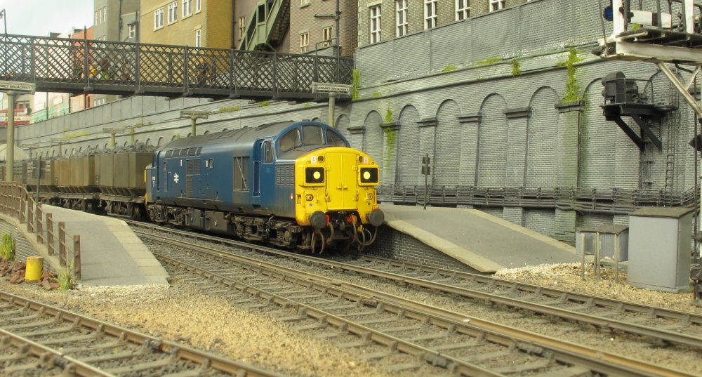 For my TOPS period, here's 37038 - a Bachmann Class 37.
![]()
 Referring back to the November 2025 update, where plans for the viaduct were outlined. I
said there that 3D printing was on a distant horizon. Well, the opportunity arose to join
a one-day course on Fusion 360 and the inevitable consequence has been the acquisition of a 3D printer!
Referring back to the November 2025 update, where plans for the viaduct were outlined. I
said there that 3D printing was on a distant horizon. Well, the opportunity arose to join
a one-day course on Fusion 360 and the inevitable consequence has been the acquisition of a 3D printer!
 A first task has been to draw up versions of the curved end girders of the viaduct, as I was
never totally happy with the ones created originally. Actually, this turned out to be quite a
task – doing the artwork so it closely matched the appearance of the Wills product involved
several iterations, but I got there in the end. Yes, you can mirror a design and produce it
double-sided, but because I wasn’t totally sure the result would be exactly the required
width, have decided to keep the front and back as separate parts, basically as with the Wills sections.
A first task has been to draw up versions of the curved end girders of the viaduct, as I was
never totally happy with the ones created originally. Actually, this turned out to be quite a
task – doing the artwork so it closely matched the appearance of the Wills product involved
several iterations, but I got there in the end. Yes, you can mirror a design and produce it
double-sided, but because I wasn’t totally sure the result would be exactly the required
width, have decided to keep the front and back as separate parts, basically as with the Wills sections.
 So this is progress on the viaduct thus far…. The ‘base’ layer has been made from 20thou
Plastikard to represent the lower flange of the girder sections. This will be strengthened
with reinforcing sections subsequently. Once this assembly has been completed, thoughts
will turn to creating the 3D artwork for the supporting columns.
So this is progress on the viaduct thus far…. The ‘base’ layer has been made from 20thou
Plastikard to represent the lower flange of the girder sections. This will be strengthened
with reinforcing sections subsequently. Once this assembly has been completed, thoughts
will turn to creating the 3D artwork for the supporting columns.
 For some light relief, this Airfix / Dapol Lowmac kit has been built, with a few refinements
to more accurately represent a Diagram 2/244 vehicle (Paul Bartlett’s Zenfolio site being
invaluable here). The work included modifying the shape of the axleboxes and replacement of
the brake lever assembly using etched brass parts (Masokits).
For some light relief, this Airfix / Dapol Lowmac kit has been built, with a few refinements
to more accurately represent a Diagram 2/244 vehicle (Paul Bartlett’s Zenfolio site being
invaluable here). The work included modifying the shape of the axleboxes and replacement of
the brake lever assembly using etched brass parts (Masokits).
 And finally I’ve built this Scalescenes garage kit to replace the cardboard mock-up currently
residing opposite Kentside station. Quite effective I thought….
And finally I’ve built this Scalescenes garage kit to replace the cardboard mock-up currently
residing opposite Kentside station. Quite effective I thought….
![]()
 Sheepcroft is a 5 Foot shunting plank and my first attempt at EM. For a beginner in this
gauge it can be a challenging learning curve getting to grips with trackwork and stock
conversion. But it is worth it when your first converted loco runs through your first
(decent) handbuilt point..
Sheepcroft is a 5 Foot shunting plank and my first attempt at EM. For a beginner in this
gauge it can be a challenging learning curve getting to grips with trackwork and stock
conversion. But it is worth it when your first converted loco runs through your first
(decent) handbuilt point..
 Some of the easiest conversions are Heljan's Bo-Bo's such as the Hymek. This has Romford
14mm coach wheels and the original gear wheels. And by using solid metal wheels the
existing pick-up arrangement can remain the same. Couplings are 3 links which look good
but can be / are fiddly to use, but shunting with them can provide a measure of
entertainment for onlookers.
Some of the easiest conversions are Heljan's Bo-Bo's such as the Hymek. This has Romford
14mm coach wheels and the original gear wheels. And by using solid metal wheels the
existing pick-up arrangement can remain the same. Couplings are 3 links which look good
but can be / are fiddly to use, but shunting with them can provide a measure of
entertainment for onlookers.
 There aren't really any hard and fast rules converting RTR stock. Some will simply accept
drop-in EM wheelsets, some require surgery to the brake blocks, other need the brakes moved
and excess chassis material removing. Fortunately the Sonic Ferry van unloading in the yard
was one of the easier ones.
There aren't really any hard and fast rules converting RTR stock. Some will simply accept
drop-in EM wheelsets, some require surgery to the brake blocks, other need the brakes moved
and excess chassis material removing. Fortunately the Sonic Ferry van unloading in the yard
was one of the easier ones.
![]()
 With the current trackwork on the new East London layout all wired, painted and weathered,
there's been more playing than there has been progress. Here Stratford allocated Class 03 -
2164 is captured during shunting moves.
With the current trackwork on the new East London layout all wired, painted and weathered,
there's been more playing than there has been progress. Here Stratford allocated Class 03 -
2164 is captured during shunting moves.
 It's enjoyable driving freight trains into the reception roads, splitting the rake and
shunting wagons into the sidings. BTH Class 15 - 8242 is seen arriving at the exchange sidings.
It's enjoyable driving freight trains into the reception roads, splitting the rake and
shunting wagons into the sidings. BTH Class 15 - 8242 is seen arriving at the exchange sidings.
 A 3-car Class 104 DMU awaits its departure time at the branch terminus station. With the
trackwork complete, I've had some fun errecting a decrepit fence and made a start on some
of the foliage and overgrown areas adjacent to the dock tramway.
Please click on the above image to view the Winter 2025 running session video from Hornsey
Broadway, and a driver's eye view along the branch line on the new layout.
A 3-car Class 104 DMU awaits its departure time at the branch terminus station. With the
trackwork complete, I've had some fun errecting a decrepit fence and made a start on some
of the foliage and overgrown areas adjacent to the dock tramway.
Please click on the above image to view the Winter 2025 running session video from Hornsey
Broadway, and a driver's eye view along the branch line on the new layout.