*********************************************************************************************************************************************
FEBRUARY 2024 UPDATE
*********************************************************************************************************************************************

KIER HARDY

Class 08 number 3690 was a Finsbury Park allocated shunter, one of a batch (D3245 to
D3708) that were built with just one vacuum exhauster cabinet on the left hand side
of the locomotive.

It was dual braked at Doncaster works in 1969, emerging with yellow
bufferbeams and the Doncaster standard black buffer shanks.

A couple of 08s which had been in the works sidings for some considerable time had been
brought into the workshops for conversion to EM and detailing work. Showing a pair of
Hornby Class 08s, a green liveried example on the left with 4 marker
lamps, and the blue one with the later arrangement which is missing the top marker
lamp. Replacement lamps have been 3D printed (featuring both full oval, and
shorter flat bottom variants), along with formed and painted conduits ready for fitting.

Simple backdating with the extra lamp, lamp brackets and conduit fitted to the blue
Class 08, making it more suitable for the 1960s / early 1970s era.

3690 is based on the Hornby model that had the later steel cab doors which
limited the choice of suitable BR(E) numbers with a single vacuum exhauster, so
replacement doors were drawn and printed to give a greater choice. In the end, a
dual braked example was chosen which required the fitment of a compressor cabinet and
shorter battery box from a spare bodyshell (which unfortunately also had the later steel doors).

Turning to the other end of the model, the left one shows a TOPS example with just
2 lower lamps, the middle one showing the addition of lamps and conduit, and the right
one with all lamps as supplied in green livery.

Turning to the Bachmann Class 08s in the fleet, they're devoid of conduits despite the
top lamp being present, so are now in the works to address some of the missing details,
and upgrading to correct the placement of handrails and pipework.

With 3690 now into service, the rest of the Hornsey Class 08 fleet are now in the
process of being updated and detailed to the same standard.

In between all this workshop shunter activity, it's nice to sit by the lineside and
watch a few trains pass by. Here a Woolwich bound 3-car BRCW Class 104 stops at Hornsey
Broadway, whilst a 4-car Cravens Class 105 set stands at platform 1 with a service to Kings Cross.
*********************************************************************************************************************************************

KARL CROWTHER

The Kendal lever frame is now painted and assembled and Iím very pleased with how itís
come out. It will probably be a while yet before I can get it incorporated into the layout.

Having got that far with the lever frame I then got distracted by Kentside Quarry! Up
until now itís just had the one siding to berth a complete train, which was proving to
be somewhat restrictive to the operation, so now seemed a good time to make a start on
the internal siding set-up. Covering 2x 4ft boards it is in essence a layout in its
own right, with some 7 turnouts. Here we see the Templot plan in the process of having
the laser-cut wooden sleepering / timbering added. For convenience Iíve split the
template at the baseboard join and at other strategic locations, to build up the track
as a series of sub-assemblies. Once the woodwork was all in place, a number of rivets
were then added at strategic locations Ė primarily on the pointwork but also a few on the plain track.

Trackwork on this section is now well-advanced with all of the rails in place, ready
for the stretcher bars and final detailing (including grinding off rivets, fitting
cosmetic chairs, fishplates etc). Note the lengths of 0.6mm copperclad strip fitted
underneath the crossing area Ė for both electrical bonding and to ensure the rails
donít move (these later ground off flush to the rail edges). Railchairs are a mix of
Exacoscale (S1 and L1), plus C&L slide chairs. The rail leading off to the lower right,
just above where the scalpel is, forms the connection to the rest of the layout.

The track on this section now all completed, just needs painting and fitting of electrical
droppers (Palatine Models). Not really evident in the photo are the dummy rail joints Ė
basically a saw cut through just the head of the rail, after which fishplates (EMGS
etched brass) could then be superglued on (Exactoscale insulated variety on the crossing
assembly of course). The final thing I then do is to cut away as much of the Templot
plan as possible ready for painting which will all be done prior to installation on the
layout, as can be seen here. That piece of ĺĒ chipboard that the previous owners of our
house left in the garage has come in very handy Ė all of the layoutís track has been built on it!
*********************************************************************************************************************************************

GREG BROOKES

Fresh onto the workbench is this Bachmann Class 40 (40063) for my TOPS fleet of models.
This particular example is one such locomotive that I drove back in the day, and is
seen here with added detail to include lifting points and bogie pivot plates. Next to
add is the bogie external vacuum and steam pipes, then finish off with some weathering.

The earlier bauxite liveried VAA for my Research Centre Tribology train has now been
fitted with replacement Taperlight suspension units, repeating the exercise from a
couple of months ago on the red & blue liveried VAA.... which now gives me the
opportunity to run the train in different eras.
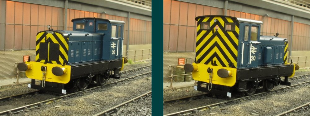
Also new to the locomotive fleet is this Ruston & Hornsby 88DS which was to be found
at Reading back in the day. It still requires some weathering, but is shown here after
being converted to EM gauge. The die-cast chassis doesn't allow the wheels to be just
pulled out, as the clearances are very tight. As well as attention to the flanges,
some material needed to be removed from the face of the wheels to reduce their thickness.
*********************************************************************************************************************************************

STEVE CARTER

After celebrating and then packing away Christmas, attention has returned to the
commercial vehicles fleet. Scratch building a replacement chassis proves to be a
relatively straightforward proposition except for their associated wheel arches /
spray flaps which are generally curvaceous in their nature. Various methods of
fabrication were tried and discounted until a repeatable method was formulated; A
shows two pieces of 15mm copper tube soft wired together such that a small gap exists
between them. By placing a hot air gun at a suitable distance (trial and error figures
heavily at this point!) then it was possible to heat a strip of 20 thou plasticard to
the extent where it becomes pliable without melting, allowing it to be forced into the
gap with a steel rule and then by using a piece of wood it can be formed around the
tube (once formed it is best to drag the assembly quickly out of the hot air flow
still using the rule / wood to hold the plastic in place until cooled). B shows the
strip after being turned around to form a second arch for a twin axle set up whilst
C depicts the two completed sets - the sets could be used 'as is' if required but in
this instance the arches have been cut apart and then rejoined to give a deeper wheel arch for each wheel.

The wheel arches seen placed loosely in situ on their intended recipient which is a Foden
S21 four axle flatbed - regular readers may notice that since its previous showing, a set
of EFE wheels from a scrap Foden S24 four axle tanker (EFE 37201) have been sourced to
give it a more realistic appearance.

A proportion of the fleet comes from Base Toys stock which unfortunately are all fitted
with the same type of wheel no matter what the manufacturer so a wheel replacement
programme has been implemented. Road Transport Images of Irvine provide a good selection
of 1:76 scale types but require soldering / gluing together being of white metal on
brass axles. As a proportion of the stock is scratch built then another approach was
sought, namely using wheels from r-t-r sources as they can be disassembled / reassembled
as required. The best method found so far for removing them from the donor vehicles is
by using a set of pointed tweezers or pliers which can be slid between the wheel and the
chassis and with a little rocking motion whilst pushing down they can be removed without too much damage.

A likely array of victims; an original Base Toys soft rubber wheel (top left) which can
be slowly drilled through and (bottom left) reamed out to a diameter suitable to allow
a push fit of axle hubs from an Oxford Diecast Bedford OX van (bottom middle and right
with original tyre on view). Double wheeled axles need an increase in depth to facilitate
their twin tyres (1.5mm thick plasticard addition seen top centre) which again are reamed
out Base Toys items to form a completed set as seen top right.

These wheels are for use with the Thornycroft Trident / scratchbuilt box van combination
and offer a vast improvement over the look of the Base Toy sets originally mooted for use.

A similar mix and match approach but this time using EFE diecast vehicles. Unlike the
unbranded Base Toys vehicles, all available EFE offerings are branded which requires
removal if they are to depict different owners. My preferred method for this is to use
a diamond lapping paste (these come with differing grit sizes, the finer the better to
avoid damaging the underlying paint finish) applied and rubbed on with a blunted wooden
cocktail stick. Carefully avoiding any details which are to remain, the paste will
eventually remove the unwanted details as seen (before and after) on this AEC Mk V cab.
Another virtue of EFE diecast vehicles is that they generally use the same cast chassis
whether it be fitted with a box van, flatbed or other body type. The two are riveted
together but can be separated by drilling off the head, the process of which makes it
a relatively simple task to then drill out and tap the remaining stem using an M2 0.4 tap.

EFE box van bodies are made from a plastic material which on their roof feature an uneven
finish (to represent a canvas covering?) which isn't entirely convincing. A smooth finish
can obtained by first sanding the roughness flat before then polishing to a shine by using
Autosol Chrome Metal polish as the polishing medium (other brands may be available!) (top
shows before, and lower the after look).

The same metal polish is also used to remove the printed details from van sides / tank
barrels without damage to the plastic and gives a sheen similar to the painted cab
finish. This example sees the cab and chassis from the AEC Mammoth Major Mk V (EFE
34405, S.H. Pratt & Co.) married to the box body from their AEC Mammoth Major Mk 1
(EFE 10501, London Carriers).

Another mash up sees the cab from a Base Toys Commer Superpoise Artic (SC-X12) married
to the body from their Thames Trader 2 Axle Box Van (TV-01) with wheels obtained from a
Classix Pocketbond Austin K2 Van (EM7612) these in turn being attached to a scratch built chassis.

The Commer cab assembly requires modifying (A) to allow it to be fitted to the new chassis
(note the cab floor is sloping upwards front to back so to avoid a drunken cab the front
of the packing piece is approx. 1mm higher than the rear). B shows a piece of Evergreen
4.8mm square tubing (Part No. 253) with a notch filed into the end ready to accept a
piece of 3.2mm diameter tube (Part No. 224) which will form the holder for the 1.8mm axle (C).

Of course being scratch built the chassis requires replacement wheel arches, and are formed
in the same manner as those done for the Foden S21 but this time using 40 thou plastic
strip (Warning: Base Toys cast chassis' are very brittle so using the wheel arches from
one or trying to modify it in any other way proves to be almost impossible!). By holding
the pieces firm against a 15mm copper tube, a bridging piece is glued into position to
ensure the they do not flare out at their bottom point and also act as a fixing point
when affixed to the chassis (a point not mentioned earlier is that it is better to place
marks on the copper tube and use these to cut the arches against it into their finished
size). The use of square tube for the chassis member ensures that when drilled through
for the rear axle then both front and rear axles will be on the same level.

Shown top is the original Thames Trader box van body; its floor is fixed into position but
with a little applied pressure it can be released and by simply turning it over and then
reinserting it, allows its original mounting points to be re-used. Having established
the correct position of the rear axle the square tube is no longer required to run the
full length of the vehicle and the axle mount is glued into position. Future works will
see a fuel tank, battery box and spare wheel added to complete the build.
*********************************************************************************************************************************************

MIKE WHITCHURCH

After the trials and tribulations with the spirelixes, efforts have been concentrated on
getting the two inner loops completed, which will give me the opportunity to
play
trains test stock conversions. The initial problem is clearing the clutter which
accumulates during work on other parts of the layout.

Once cleared up, a little track laying commenced. A very useful aid for those of us not
blessed with adequate track laying skills are these custom sized curve alignment guides
from Gavin at Stoneybridge Structures. I can't thank Gavin enough for his help and
perseverance with these, especially as we finished up doing battle with Correos, who, if
you think Royal Mail are bad you ain't seen nothing yet.

So finally 2 tracks have been completed and running can commence!
*********************************************************************************************************************************************

JONNY DUFFETT
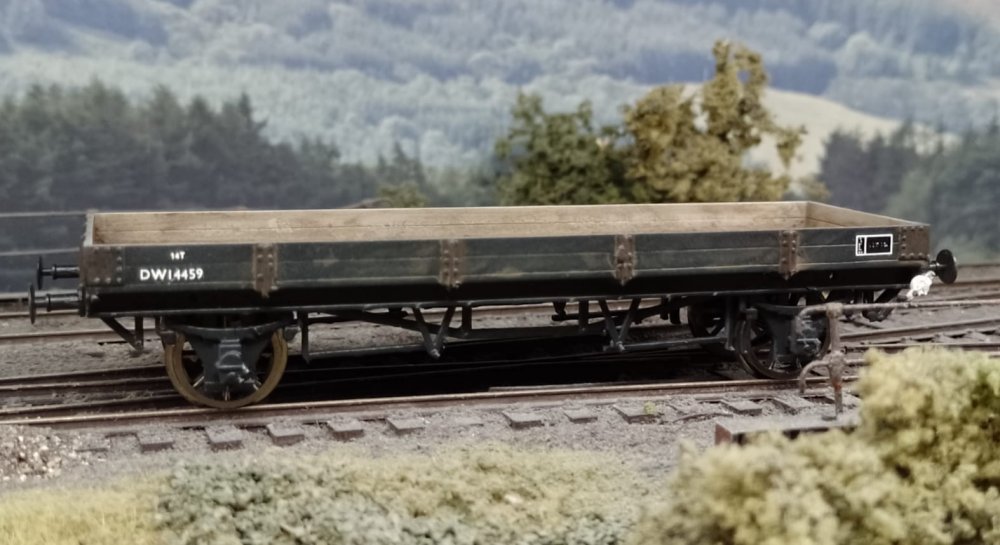
Ex-GWR Whiting. These wagons were used by the S&T department based at Reading.
This version has the old Dean / Churchward brakegear.
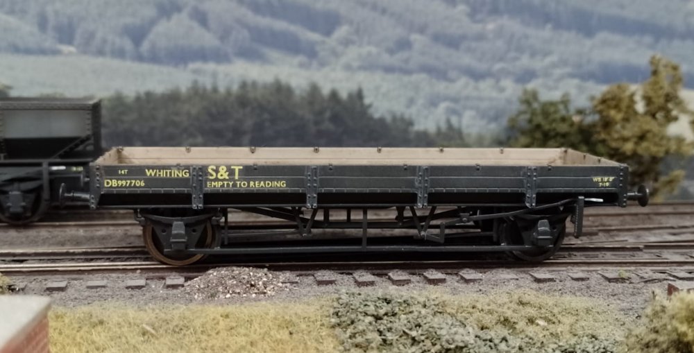
BR built some more Whitings to dia 1/622. There were a few batches from both Swindon
and Wolverton works. Transfers are from CCT.
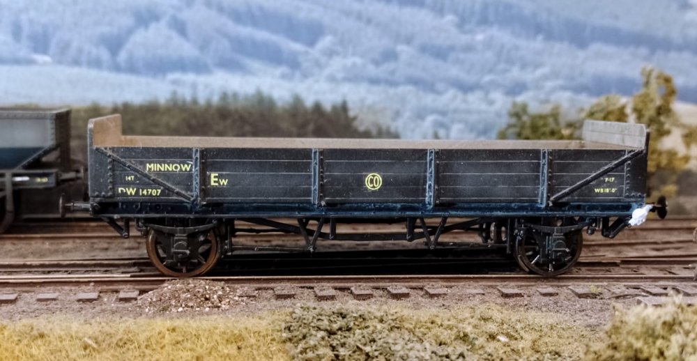
Ex-GWR Minnow. These wagons were built to carry sleepers for the engineers department.
They had 4 plank sides and 6 plank ends. There were a few different diagrams and some
of the earlier wagons had a shorter wheelbase to this one shown.
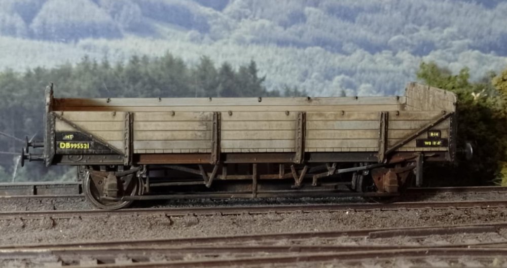
BR built Minnow with detail differences to the GWR type. Many of these wagons were
stripped of their bodywork to produce flat wagons on which machinery was added to
work with Matisa ballast cleaners.
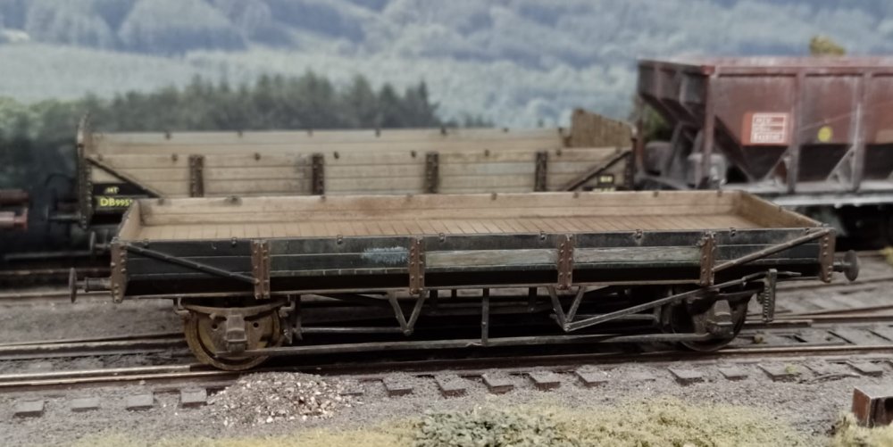
Here's a rare one. Awaiting decals is this cut-down Minnow which will become DB995500.
The planks were reduced to just 2 high all around. The other Minnow DB995519 was
built with just 2 planks to Whiting standard.
My 3D designs are available free at
Thingiverse
for you to print yourself, or visit
the links page for printing service options, including the latest additions of
Class 08 doors and lamps as featured top of page.
*********************************************************************************************************************************************


