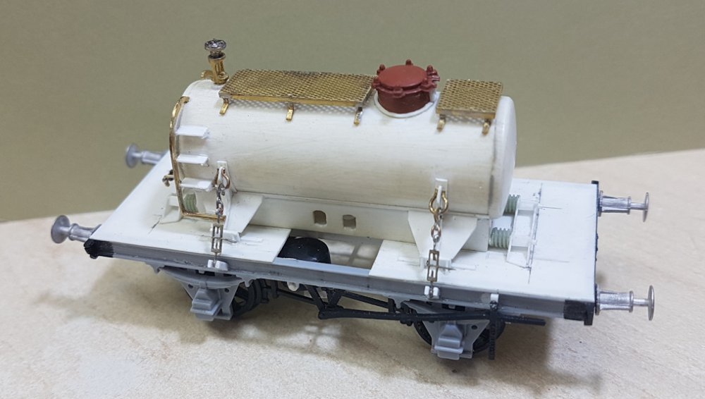
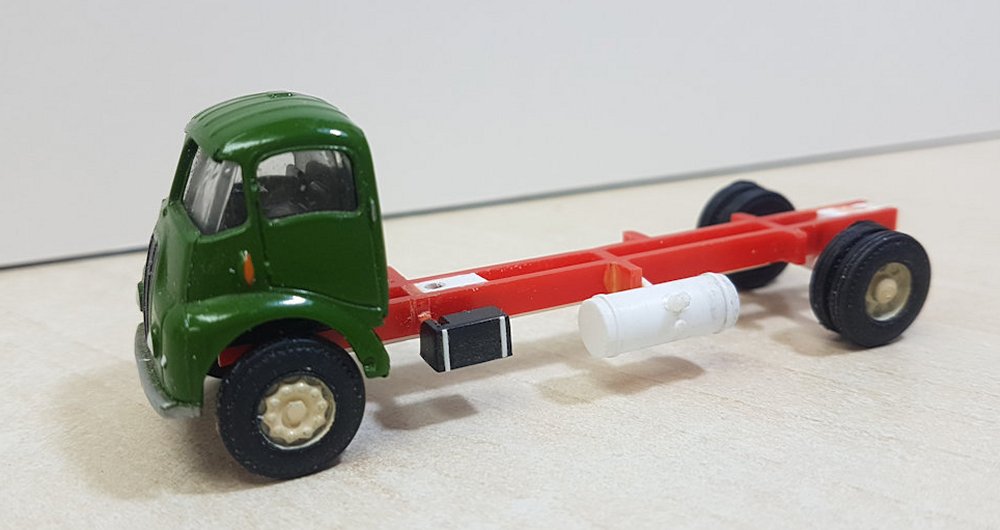
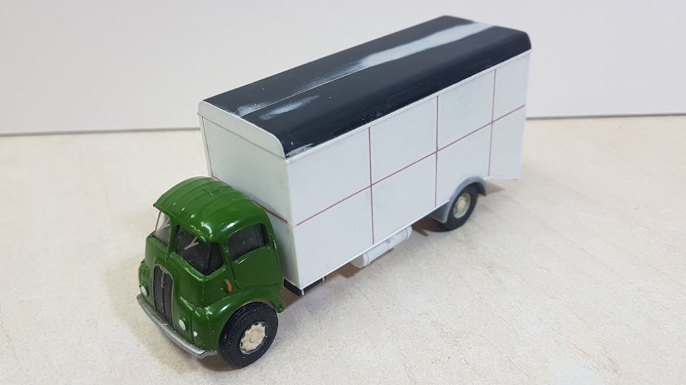
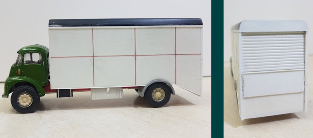
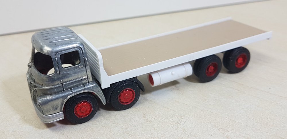
The tractor unit seen in company with a scratch built flatbed to give a 4 axle vehicle.
The wheel sets are presently Base Toy axles, as those fitted to the Lledo model are
permanently coupled together.
The underside shows how the tractor unit slides into position beneath the flatbed. The
axles are held in place using Evergreen 1/8th" tube (Part No. 224) through which the
Base Toys axles can pass. The rear two axle mounts are made by combining this tube with
Evergreen 4.8mm Square Tube (Part No. 253) which ensures level wheel sets are obtained!
*********************************************************************************************************************************************

KARL CROWTHER

Good progress with the signals this month. However, following on from what I said last
time about the 3D printed lamp / arm pivot assemblies – yes, one of the pivots broke off
while I was in the process of getting an arm fitted. I managed to re-attach the pivot
with superglue, but then on another of the signals the same happened again! Not wanting
to take any further chances, the pivots on this signal were all cut off and replaced
with brass tube, soldered carefully into position. I’m now hoping that those on the
remaining signals (5 arms in total) will hold. I will stick to brass tube bearings in
future! Many coats of paint were needed on the 3D printed lamps to prevent the entire
body from glowing (though I will admit they were intended for illumination by fibre optic, not LED).

More arms fitted – these being the 3-doll Kendal Inner Home signal and the other being
the starter for platforms 2 & 2. With the signals as a whole I’ve tried to encompass
as much variety as to structures as possible. Hence here we have a welded stem bracket,
with the other being a broad flanged beam type. The wires emerging from the base pf the
posts, are the positive 12V DC feed for the LEDs – the negative polarity being formed
by the signal structure itself. For 12V DC these LEDs need at least a 1,000 Ohm resistor
– the next image shows how this was done…..
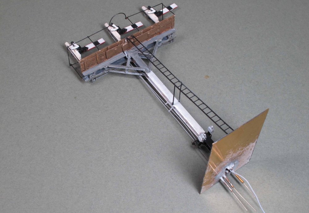
Beneath the platforms a piece of very thin copperclad, suitably gapped, was made to form
a ‘circuit board’ for connecting the LEDs – the positive feed to each being via a 3.3K
Ohm surface mount resistor. The negative leads from the LEDs are then soldered directly
to the underside of the platform, thus making the signal structure itself, the return
current path. The copperclad strip can just me made out in the photo – having been
overpainted with the ‘wood’ colour of the platform, together with the grey decoder wire
which in this case was in this case passed down within the channel of the main signal
post on the face that will be away from the viewing side.

The Heversham Down home signal is a tubular post bracket. Like the other bracket signals
it has the LMS pattern torsion bar arrangement to work the arms – in practice probably
easier than cranks in model form, even though the parts need scratchbuilding. This is
the signal where I replaced the 3D printed arm pivot bearings with brass tube. All the
signals just need the post caps to be added. Next month, hopefully some progress on the lever frames…..
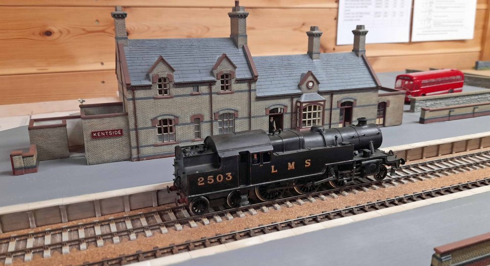
A very pleasant surprise at the latest running day was to have one of the late David
Jenkinson’s ex-Marthwaite locos turn up for a visit to the layout. Being analogue it
could only do couple of trips round the main circuit, but it was fantastic to have it
making a guest appearance on The Kentside Branch.
*********************************************************************************************************************************************

HYWEL THOMAS

Over the last few months I’ve been enjoying running trains on Morfa Bank, with little
to report, however work has continued on the new 1970s South American layout and the
latest project may interest readers. The new layout rises steeply from a small yard
up into mountains and includes a village on the mid level, as well as a gorge and a
lot of bridges. This update shows the construction of mock-up buildings for the
village ahead of the longer-term modelling in detail. This is the site of the first
block. The Magnorail track has been laid and tested but awaits a road surface. The
steps rise from the end of a small alley with the upper path marking the position
of the ground floors of the next level up.

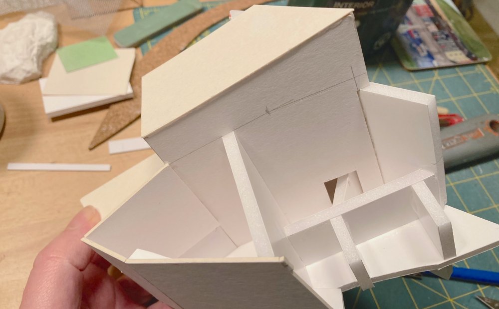
The mock-ups were built of various off-cuts of card, including cereal packets and foam
board. This was the first section with the plan being to replicate the kind of ramshackle
planning often visible in older settlements, especially in industrial areas pre-1970s.
Nowadays most groupings like this would have been swept away by redevelopment. The
cutting was done by trial and error with any complex pieces having the measurements
marked on so they could be easily replicated when the permanent structures are built.
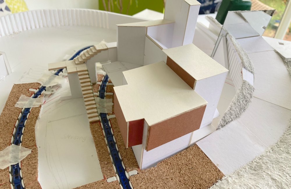
This is the first section in place. The various overhangs will disguise the Magnorail
cyclist as it heads around the turning loop beneath the next level. The road to the
right runs steeply up to that level so the buildings need to rise up with it. An angled
mirror has been included at the top of the rise to give the impression of the road
continuing out of site around the bend as it continues to climb upwards.
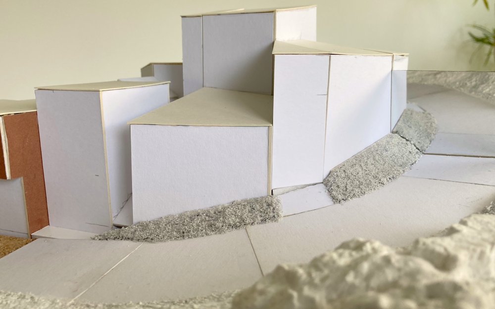
This is the second section and illustrates the very crude and basic construction but has
proved ideal to gain a feel for the scene ahead of final construction. This method
allows for easy changes if the view doesn’t work or a building feels too overpowering.
I know a lot of people use small scale models for this stage of proceedings but I feel
I can better visualise something at full 1/76th size.
Here we see that second section complete and slotted in alongside the first. Also
illustrated is the steep gradient on the road and the view through the angled mirror
following the curve of that road up and around the bend.
This view shows how the two sections fit exactly together, like a 3D jigsaw, and
illustrates the very irregular roof line, which will add some interest and mystery to
the settlement. Just like on Morfa Bank I wanted to create a number of paths and
passageways that wound up through the scene, inviting exploration. The next level up
will be higher than the tallest roof seen here and will continue the theme of the lower level.

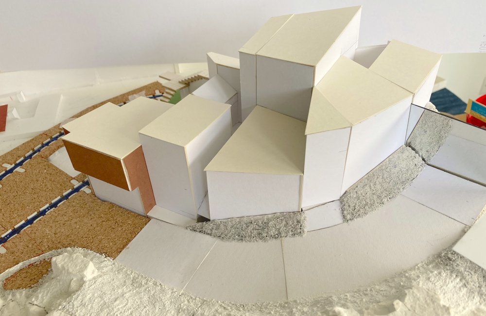
Looking directly down on this part of the village illustrates how the different buildings
interact with each other. And how they are designed to hide the return loop of the
Magnorail system. This also shows how the scenery has been continued beyond the mirror
to the backscene location, the near side of which will be disguised by another building,
the base of which can be seen at the bottom of the image. The top surface of the mirror
will be hidden beneath a run of electrical cables from a post in the embankment verge.

Finally, a view from lower down the mountainside showing how the cluster of buildings
will rise up towards the back of the layout, as well as rising left to right as the road
climbs higher. The rock surfaces obviously still need colouring! The split line visible
running through these is the join between the bottom and top halves of the layout,
allowing track cleaning and also maintenance of the Magnorail system when needed. This
will be disguised with vegetation and stone rubble as the scenery develops.
*********************************************************************************************************************************************

JONNY DUFFETT

The latest project is this Gypsum hopper wagon diagram 1/168 (PG001A). There were
only 39 of these wagons built in 1970 to take gypsum to the Northfleet Cement
works in Kent, which were designed to work on the Merry Go Round loading and unloading
technique, and look like a smaller version of the widespread Coal MGR wagons.

I am not aware of any existing models of this curious wagon being available in any scale, so
there are no transfers available so far. This model has been made using the resin printing technique.
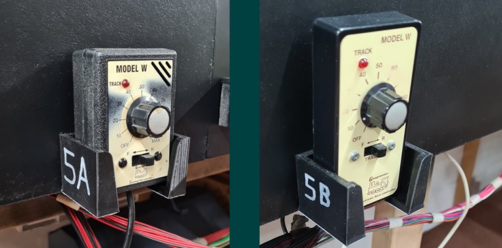
For durability and strength, these controller holsters have been produced on the filament
printer, and will accomodate a wide variety of controller styles. All my 3D designs are
available as a free download at
Thingiverse
for you to print yourself, or visit
the links page for printing service options.
*********************************************************************************************************************************************

GREG BROOKES
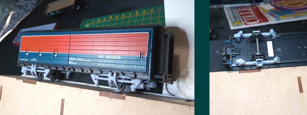
Hot off Jonny's machine are these Taperlight suspension units for the Bachmann VAA as
used in the Research Centre's Tribology train.

Another nice and easy fitment shown after painting. Consistency of the suspension units
and the potential scratchbuilding time makes these an ideal 3D printing project.

Other recent projects include the fitment of wing mirrors to my fleet of commercial
vehicles, using the Scale Link fret SLF137.
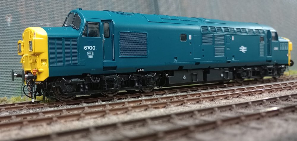
New to the Shenston Road locomotive fleet is this Accurascale Class 37 - still
awaiting weathering. Considering the model is marketed with replacement 'drop in'
wheelsets for EM & P4, it would be nice to be able to drop the wheels in... Instead,
the process involves the use of a large swear jar, the difficult removal of a 6-clip
keeper plate and dismantling the brake gear and bogie sideframes. Tri-ang had a better
idea back in the 1960s using just a couple of screws to make wheel removal and
lubrication / maintenance a breeze! It's a shame it's so overcomplicated - one can only
hope the forthcoming Class 31 will be more 'drop in' friendly.

Warship 870 is now finished and into service, seen here at Hornsey Broadway.
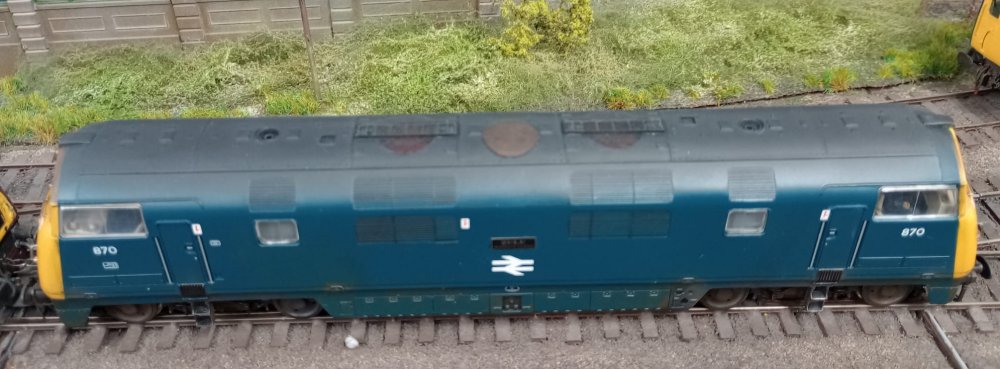
It wasn't the easiest of the class to model, as the cab top air horn pods had to be made
and fitted, a Spanner boiler exhaust fashioned on the roof, and the model's moulded
boiler grill filled in.
*********************************************************************************************************************************************

STEVE HARROD

6323 is captured on the Newton Abbot Works traverser. Just
the addition of windscreen wipers and this will be another model ticked off my list.
*********************************************************************************************************************************************

KIER HARDY
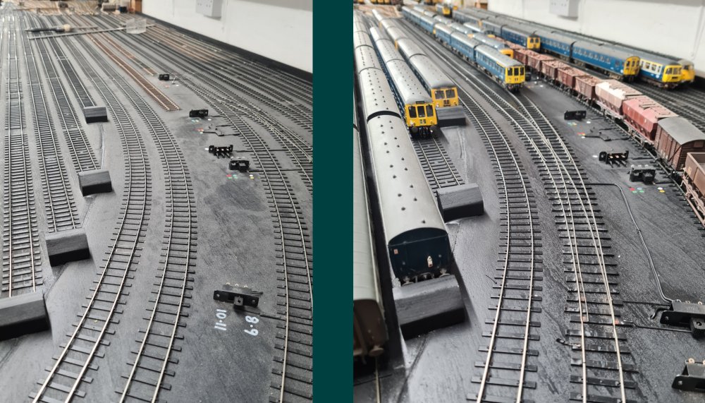
Another cleaning and maintenance session was carried out this month in the South Sidings,
with one of the isolated roads commissioned (Road 6) with the addition of a curved point
which I had laying around for a while. It fits just perfectly and allows stabling of a 6
coach rake or a couple of DMU sets. Road 7 will remain isolated and is used as the works
siding for locomotives awaiting attention at the bench.

The layout continues to entertain generations young and old, so from Polly Pocket, Peppa Pig,
Antelope and the Mighty Max crew, here's wishing everyone 'seasons
greetings' and all the best for 2024.
*********************************************************************************************************************************************


